
Connection method of hydraulic cylinder and pump station
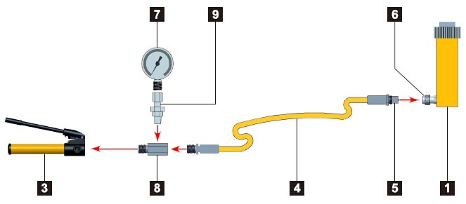
Single-acting push application,such as in a press
The hand pump offers controlled cylinder advance, but may require many hand pump strokes in longer stroke applications when the cylinder capacity is 25 ton or above.
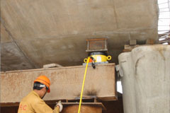
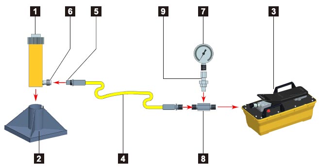
Single-acting cylinder with longer stroke used for lifting applications
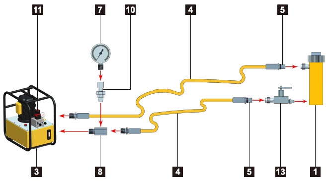
Double-acting cylinder set-up used fro lifting applications where a slow controlled descent of the load must be maintained
Double-acting cylinder set-up used in a push/pull application
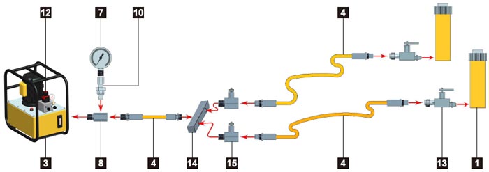
Two point lifting set-up using single-acting cylinders
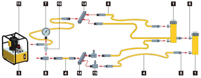
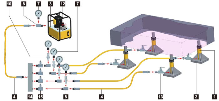
Four point lifting set-up, using single-acting cylinders and directional control valves
Notice:
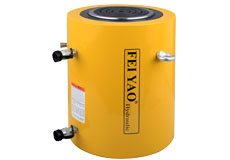
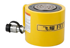
1. CylinderApplies hydraulic force. 2. Cylinder Base Plate
For applications like lifting where additional cylinder stability is required. 3. Pump
Provides hydraulic flow. 4. Hose
Transport hydraulic fluid. 5. Male Coupler
For quick connection of the hose to system components. 6. Female Coupler
For quick connection of the hose end to system components 7. Gauge
To monitor pressure of the hydraulic circuit. 8. Gauge Adaptor
For quick and easy gauge installation. 9. Swivel Connector
Allows proper alignment of valves and/or gauge. Used when units being connected cannot be rotated. 10. Auto-Damper Valve V-10
Used to protect gauge from damage due to sudden pressure pulses in the system. Needs no adjustment and allows correct positioning of gauge, prior to tightening. 11. 4-way Directional Control Valve
Controls the direction of hydraulic fluid in a double-acting system. 12. 3-ways directional Control Valve
Controls the direction of hydraulic fluid in a single-acting system. 13. Safety Holding Valve
Controls load descent in lifting applications. 14. Manifold
Allows distribution of hydraulic fluid from one power source to several cylinders. 15. Needle Valve
Regulates the flow of hydraulic fluid to or from the cylinders.